MPLAB First Steps
Installation
Install MPLAB X IDE
Install MPLAB X IDE through the official Microchip site: MPLAB X IDE
Install XC32 Compiler
Install the XC32 COmpilers from Microchip: MPLAB xC32 Compilers
Your First Bare-Metal Project
- Create a New Project
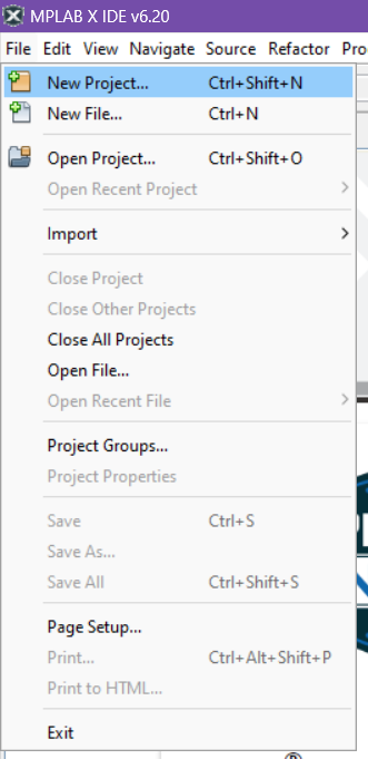
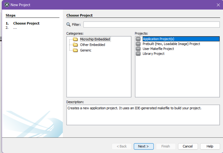
- Choose
Application Project(s)then clickNext >
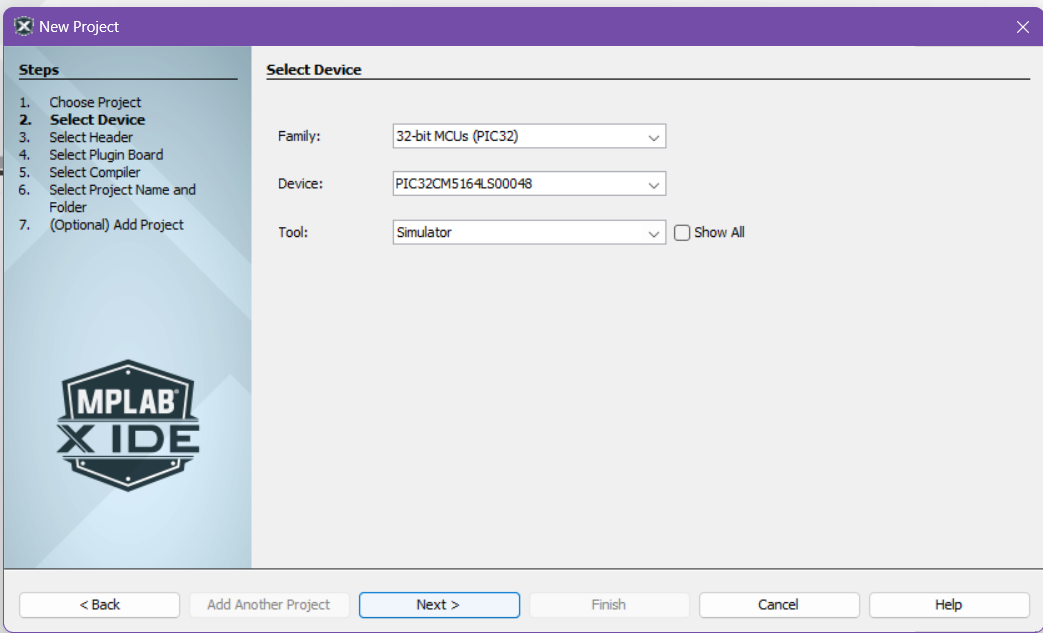
- Choose the following for
2. Select DeviceDevice:PIC32CM5164LS00048Tool:Simulator
note: you can always change the tool later, will be useful once we move from using the simulator to actual hardware
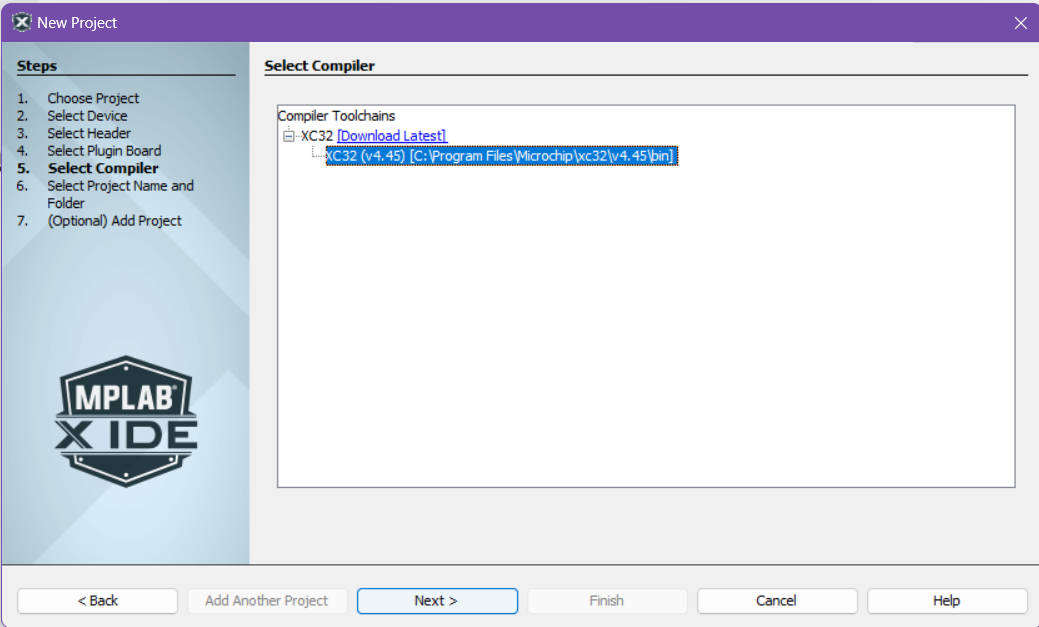
- Choose a installed XC32 Compiler
- note: if you do not see options for compilers, make you have properly installed the XC32 Compilers from the
Install XC32 CompilersStep
- note: if you do not see options for compilers, make you have properly installed the XC32 Compilers from the
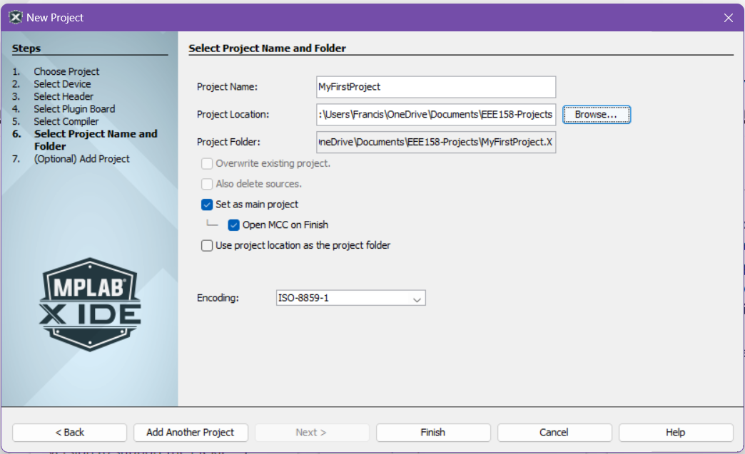
- Select where to save your Project on your local machine then click
Finish
note: We suggest creating a new folder within another folder when you create a project as another folder will be generated in the same directory as the path you choose here (i.e. if you plan on storing all your Projects in a folder called MyProjects, create a folder MyProjects/MyFirstProject and choose MyFirstProject as the place to save)
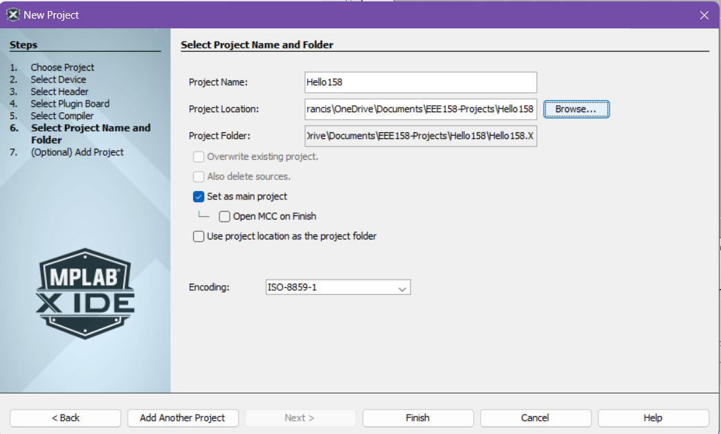
note: Unlick the `Open MCC on Finish option as we won’t be using that for now
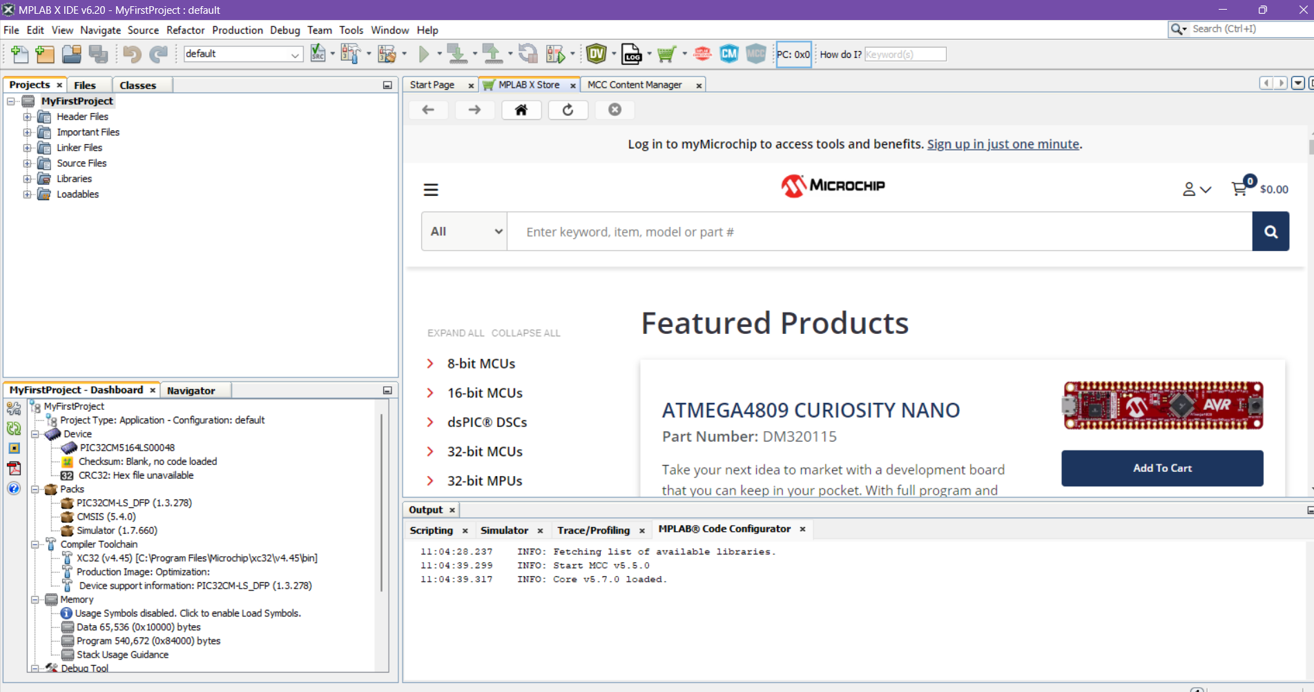
- Your First Project should now initialize
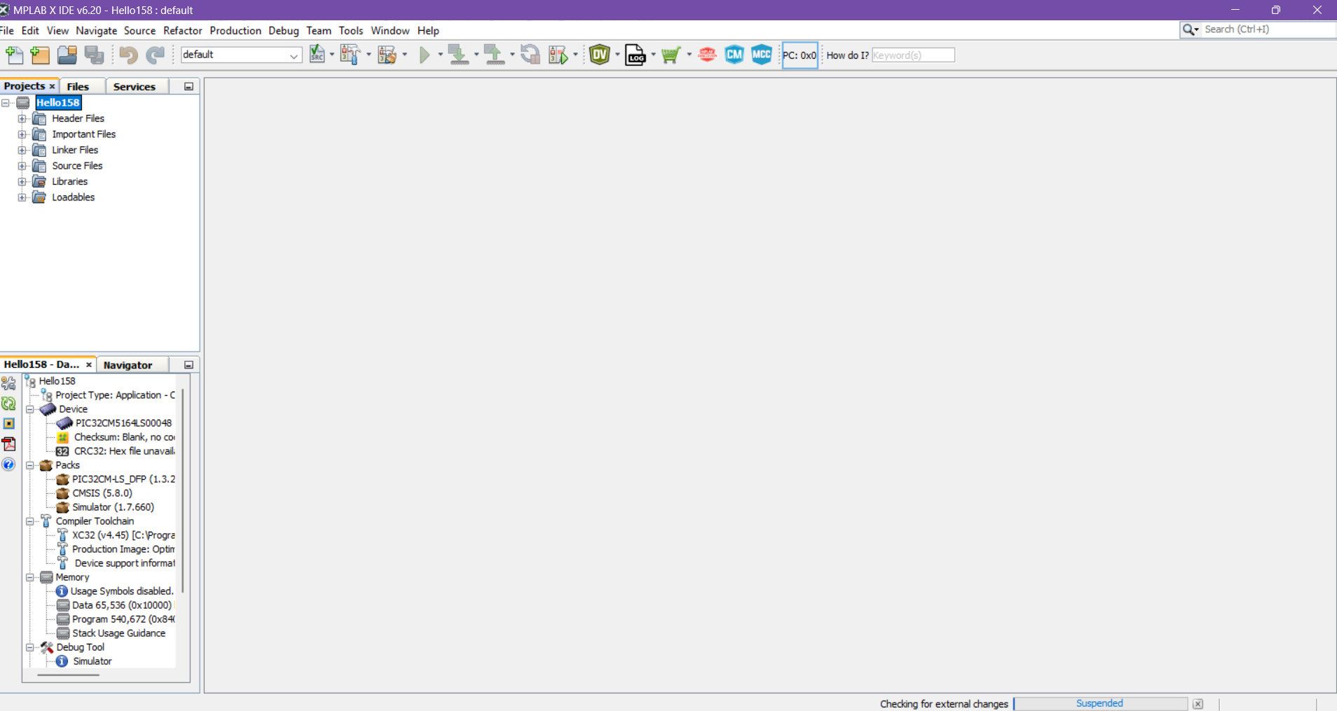
Let’s now proceed to creating a main.c file so we can start coding our application.
Guided Exercise: “Blinky!”
Blinky!
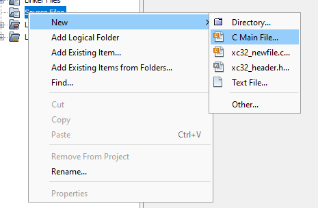
Create a main.c file. Right click on the Source Files of the Project Tab then click New and C Main File
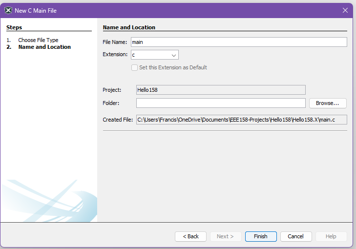
Proceed to input the following code into main.c
// All register names are defined here.
#include <xc.h>
// Naive software delay; approx. 1us / cycle
void crude_delay_ms(int ms)
{
while (ms > 0) {
for (int i = 0; i < 1000; ++i) {
asm("nop");
}
--ms;
}
}
/*
* NOTE: Most of my students seem to recall the member-access operator when
* using the term 'class' rather than 'struct'.
*
* If 'a' is the object itself, or a C++ rvalue:
* a.b()
*
* If 'a' is a pointer:
* (*a).b()
* - or -
* a->b()
*/
int main(void)
{
/*
* Configure PA15 (Port Group A, Bit 15)
*
* 'PORT_SEC_REGS' --> All port I/O registers
* 'GROUP' --> Array of port groups (0 = 'A', 1 = 'B', etc.)
* 'PORT_???' --> Register named '???'
*/
// NOTE: Some review of C/C++ bitwise operations may be in order.
PORT_SEC_REGS->GROUP[0].PORT_OUT &= ~(1 << 15);
PORT_SEC_REGS->GROUP[0].PORT_DIR |= (1 << 15);
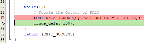
// Nowhere to return to, hence the infinite loop
for (;;) {
crude_delay_ms(200);
// NOTE: A '1' in an XOR mask causes a toggle.
PORT_SEC_REGS->GROUP[0].PORT_OUT ^= (1 << 15);
}
// Not expected to be run at all
return 1;
}
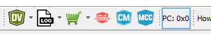
Let us first try Building our Application. Press the Build Icon to compile your project. It’s the one that looks like a hammer

If it builds, we are now ready to try and debug your application.
Simulator Debugging
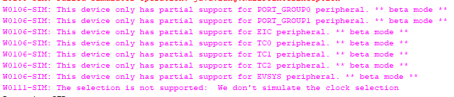
note: the simulator has limited functionality in simulating the PORT peripheral
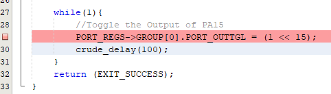
Include a breakpoint in your program by clicking on the line number on the left side of the code editor
Click on the Debug Main Project button on the ribbon to begin Simulator Debugging.
Application Execution Control
These buttons on the ribbon will allow you to control the debugging of your application.
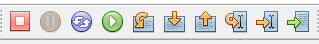
Finish Debugger Session- End DebuggingPause- Pause Application ExecutionReset- Reset Application ExecutionContinue- Resume Application ExecutionStep Over- Step over a line of your ApplicationStep Into- Step into a a method in your ApplicationStep Out- Step out of a method in your applicationRun to CursorSet PC at CursorFocus Cursor at PC
Your debugger should stop at the break point we set earlier
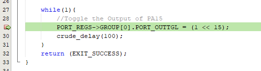
Press the Step Over Button and you should go into the next line of the Application code
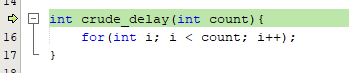
Now press the Step Into Button and you should go into the crude_delay method
Press the Continue button and after a while, you should hit the breakpoint again
Target Memory Views
Target memory views allows us to look at the contents of the memory of our device under test (DUT). You can open this by navigating in the ribbon. Window -> Target Memory Views
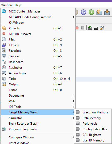
Let’s try and open up the Peripherals Memory View.
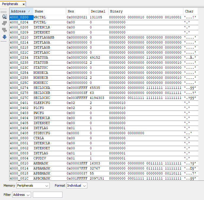
This allows us to directly check the contents of the registers and is useful for debugging.
Logic Analyzer
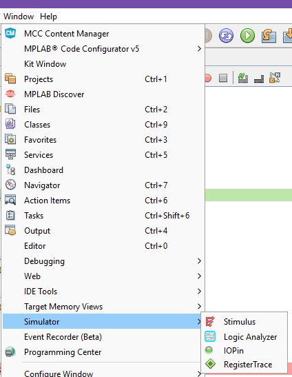
You can open up the logic analyzer by going to ‘Window’ -> ‘Simulator’ -> ‘Logic Analyzer’
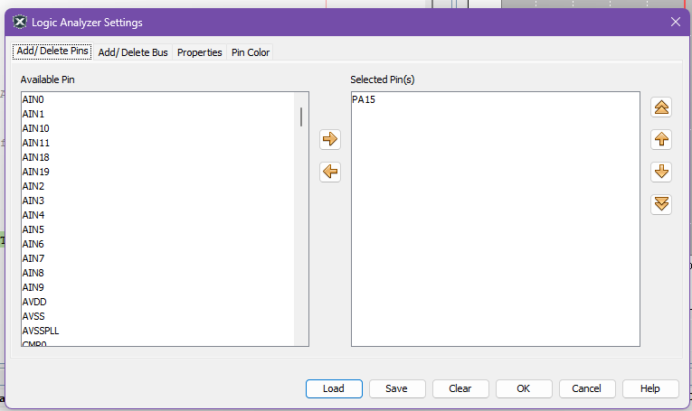
You can watch over a pin’s state by adding it. Press the Settings icon on the logic analyzer window and add PA15 to Selected Pins

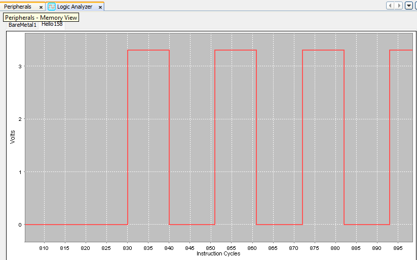
You can now use the Logic Analyzer to view how PA15 toggles between 0V and 3.3V
Hardware Debugging
Hardware debugging is similar to Simulator debugging and you can perform any of the Application Execution Controls and Memory View functionality.
To change the Tool from Simulator to you on-board debugger
- Plug in your Curiosity Nano board to your machine
- Click on
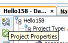
Project Properties
- Change the
Connected Hardware Toolto you on-board debugger
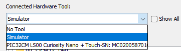
- When you perform debugging now, the program will first upload to your microcontroller and you can proceed with debugging.
Your First MCC Project
MPLAB Code Configurator (MCC) is a tool from Microchip which allows us to easily configure our Microcontroller by automatically creating macros we can use for our code. Let’s try and use it.
- Create a New Project
- Choose
Application Project(s)then clickNext >
- Choose the following for
2. Select DeviceDevice:PIC32CM5164LS00048Tool:Simulator
note: you can always change the tool later, will be useful once we move from using the simulator to actual hardware
- Choose a installed XC32 Compiler
- note: if you do not see options for compilers, make you have properly installed the XC32 Compilers from the
Install XC32 CompilersStep
- note: if you do not see options for compilers, make you have properly installed the XC32 Compilers from the
- Select where to save your Project on your local machine then click
Finish
note: We suggest creating a new folder within another folder when you create a project as another folder will be generated in the same directory as the path you choose here (i.e. if you plan on storing all your Projects in a folder called MyProjects, create a folder MyProjects/MyFirstProject and choose MyFirstProject as the place to save)
- Your First Project should now initialize
- We now proceed to setting up the MPLAB Code Configurator, It will either open up automatically or you can open it by clicking on the
MCCicon on the top ribbon
MPLAB Code Configurator
- Download content for MPLAB Code Configurator (MCC)
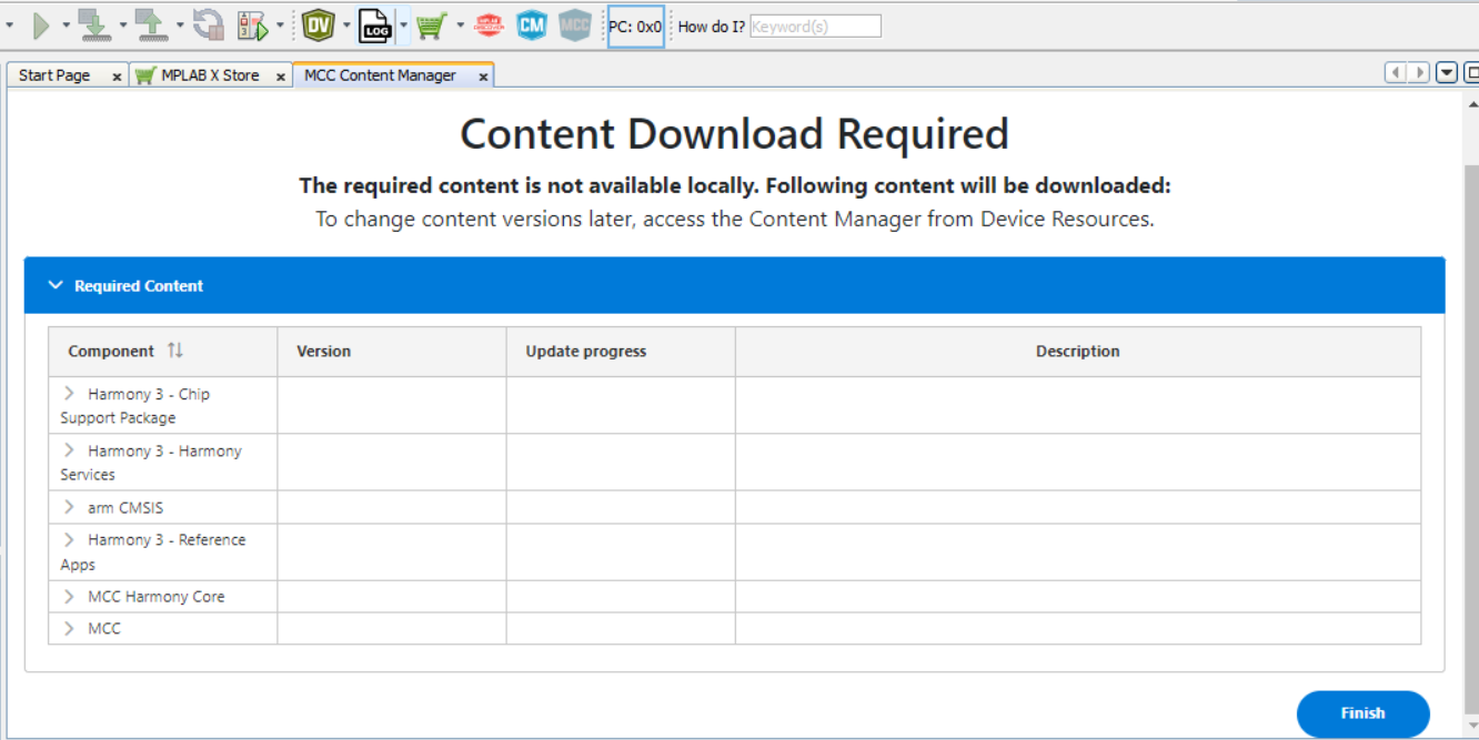
- On your first time opening, MCC will automatically ask you to download some files.
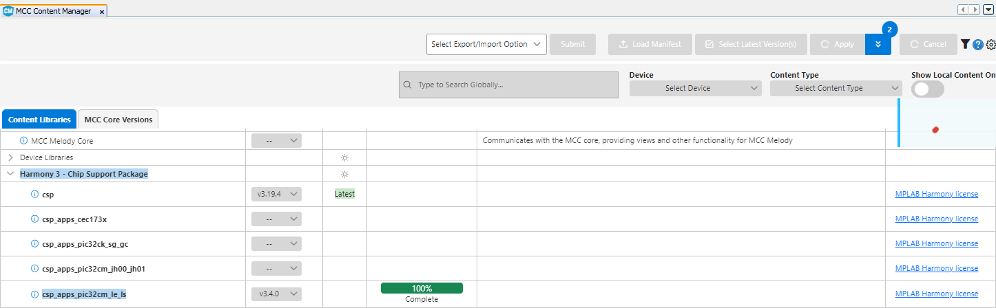
Board Packages
- Chip Support Package: proceed to also include
csp_apps_pic32cm_le_lsfrom underHarmony 3 - Chip Support Packages
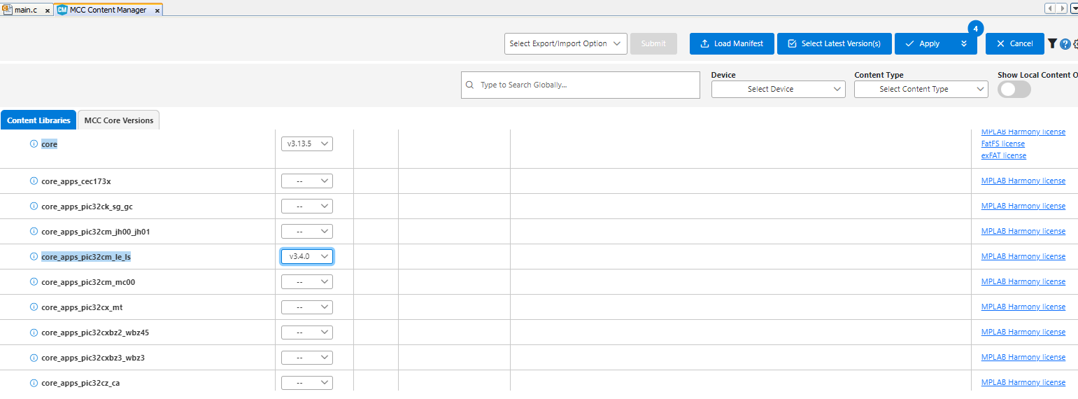
- Core Apps Package: proceed to also include
core_apps_pic32cm_le_lsfrom underHarmony 3 - Core
note: you can also add these packages later by opening up the Content Manager (CM button beside MCC) if you don’t install them now
MCC Harmony Windows
We now proceed with using MCC to easily create some configurations for our Microcontroller
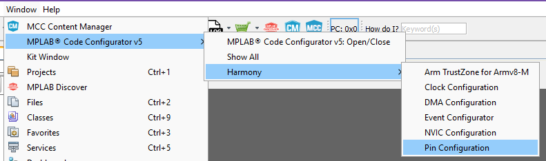
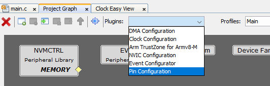
Open up MCC and navigate to Pin Configuration either through the ribbon or through the Project Graph
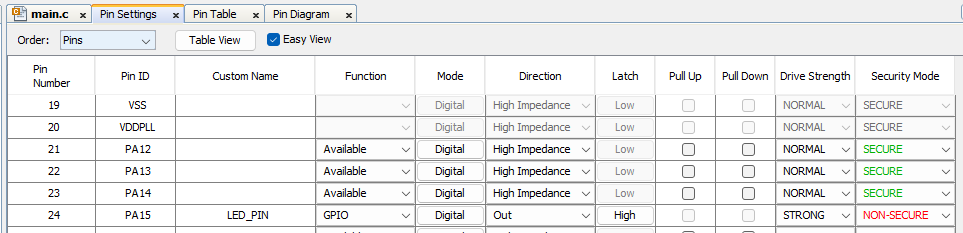
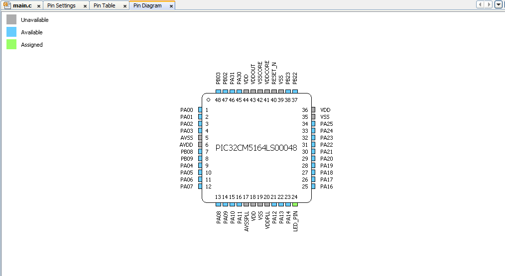
We can use a GUI to set up the pins of our Microcontroller. Proceed to set up PA15 as Output Pin as shown. Take note of the Security Mode being set as NON-SECURE as well.
- Click on Generate to generate your configuration code

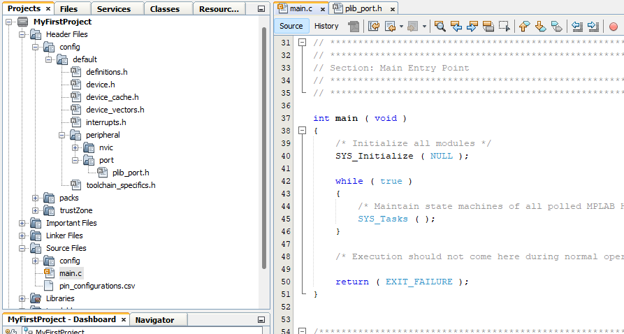
You should now see in your Project folder more files, these were auto generated by MCC. The interesting one here is the header file plib_port.h
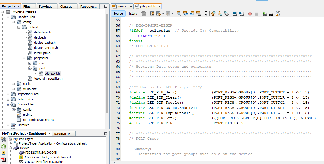
You can use these newly declared definition in you code to control the Pin.
- Go to
main.cunderSource Files
Here is where you can start creating your application. Let’s blink try and blink an LED by switching a pin between HIGH and LOW.
Guided Exercise: “MCC-Blinky!”
Blinky!
- in
main.cadd the function callLED_PIN_Toggle();and also thiscrude_delay_ms()function beforemain()
int crude_ms_delay(int ms){
    int count = 0;
    unsigned int delay_count = ms * 12000;

    while(count < delay_count){
        asm("nop");
        count = count + 1;
    }
    return 0;
}


int main ( void )
{
    /* Initialize all modules */
    SYS_Initialize ( NULL );

    while ( true )
    {
        LED_PIN_Toggle();
        crude_ms_delay(1000);
        /* Maintain state machines of all polled MPLAB Harmony modules. */
        SYS_Tasks ( );
    }

    /* Execution should not come here during normal operation */

    return ( EXIT_FAILURE );
}
Let us first try Building our Application. Press the Build Icon to compile your project. It’s the one that looks like a hammer
If it builds, we are now ready to try and debug your application.